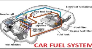
The continuous injection is the simplest and least costly method of injecting fuel from injectors. The continuous injection works by injecting a fuel mixture spray into the intake manifold, where it is ready to flow into the individual cylinders when the inlet valves open. The fuel mixture is controlled through variation in the pressure of the fuel sent to the injectors from the fuel pump.
In multi-point injection, the fuel is made into a homogeneous mixture through the turbulence in the cylinders. The more favored method of fuel injection is through sequential or timed injection, which injects the fuel for limited time periods, usually once for every revolution of the crankshaft.
Fuel is maintained at a constant pressure combating the difficulty related to the small-time lag in the electronic control between receiving and sending signals between sensors, the computer, and then the fuel pump. 34 Generally, the timing of the opening of the fuel injectors is fixed and changes are produced from varying durations of time before the closing of the injectors.
With almost instant responses from the electronic control computer, the air to fuel mixture can be closely controlled. Further development produced the simultaneous double-fire injection or phased injection system which allows for extremely accurate regulation of the air to fuel mixture.
This is accomplished by injection of fuel into the ports as the inlet valves open, consequently only once every two revolutions of the crankshaft. The numerous advantages of sequential and phased injection arise from the accurate monitoring of the engine management computer system which helps avoid numerous problems of engine operations, through the implementation of a multitude of sensors such as the detonation sensor and crankshaft angle sensor.
There are four types of flow sensors implemented in electronic fuel injection systems the suspended-plate type flow sensor, the swinging-gate type flow sensor, the manifold absolute pressure (MAP) sensor, and the mass-flow sensor. The suspended-plate type flow sensor is comprised of a circular plate pivoting on the opposite end of an arm, balanced by a small weight, which suspends the plate in the horizontal plane within a circular throat.
When the engine is turned off, the plate then returns to its equilibrium position in the narrowest section of the complex tapered throat. The entering air then pushes the plate against the resistance produced from a hydraulically actuated control plunger, which depresses a roller on a small level arm thereby controlling the idle setting for the engine with a screw 35 Figure 4.1: Swing Gate Volume Flow Sensor stop. During sudden acceleration, the plate momentarily over swings, increasing the supplied mixture and then returning to the equilibrium position.
The second type of flow sensor, the swinging-gate sensor, or air vane sensor, illustrated, is comprised of a housing and internal vane which is deflected by the incoming air into the engine. The vane is spring-loaded lightly and pivots from the force of the incoming air.
The sensor incorporates a damper that pivots with the vane to negate the effects of pulsing air distorting the reading of the actual airflow through the sensor. The third flow sensor, the MAP sensor works by theoretically calculating the mass of the air entering the intake system.
Last word
The manifold absolute pressure sensor 36 senses the absolute pressure in the intake manifold, and then through calculations in the engine management system, finds out the air mass traveling through the intake. The disadvantage to this type of sensor is that it has general calculations which rely on standard conditions, such as temperature, which fluctuates in real-world conditions


