Interconnected front/rear suspension
The concept of interconnecting the front and rear suspensions to reduce the period in pitch is an old one. A mechanical interconnect was developed for the little Citroen 2CV and this, despite an obvious lack of roll stiffness, gave a very good ride over rough terrain for such a tiny vehicle. Let us consider as a first step a simple system where both front and rear suspensions share the same spring, i.e. one spring per side.
With a perfectly symmetrical system, the sprung mass could not oscillate in pitch, since a downforce at A would deflect the front spring connection a distance x, and this would be balanced by a force at the rear of identical value which would deflect the rear spring connection an equal distance x in the same direction. Spring deflection would therefore only occur in bump and rebound, not in pitch. Before we rush off to the Patent Office, let us consider what would happen to such a vehicle on the road.
There would be no spring force to act against this inertia force and the body would tip backward hard against the limit stops. Light braking would produce the opposite reaction since the system is completely unstable in pitch.
The Citroen 2CV
Additional springs without interconnection are seen to be essential to achieve a practical interconnected suspension. This can be seen on the Citroen 2CV, shown schematically in Fig. 10.2 in which the two main springs 5 f and 5 are enclosed in a ‘floating’ cylinder, which is mounted between auxiliary springs Sf and s r with abutments against the sprung mass. In the later examples of the 2CV, these auxiliary springs are made of rubber.
This would give a natural frequency in pitch (since natural frequencies vary as the square root of spring rates) of about 85% of the natural frequency in bump and rebound. The above analysis is an oversimplification but serves to illustrate the Citroen principle.
The Moulton hydromantic suspension
The first production application of Hydromantic suspension, the name adopted by Mouton Developments Ltd, was to the BMC 1100. An idealized diagram of the behavior of hydrolastic suspension on a variant of the original ADO 17 design, the MG 1100.
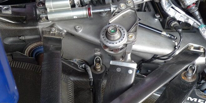
At the base is a sheet metal partition. The outer rim of this and the lower extremity of the casing are swigged around the reinforced rim of the molded rubber/nylon reinforced diaphragm. Two rubber one-way valves in the center of the partition permit flow in both directions. These two valves, together with the small bleed hole, replace the conventional damper system. The fluid on both sides of the partition is a mixture of water, alcohol, and an anti-corrosion agent. The piston rod which is located in the center of the diaphragm is connected to the suspension links and moves up and down with wheel movements.
Interconnection
The Hydromantic spring elements on the same side of the car are interconnected by small-bore piping. The pipe connection ‘cannot be seen in Fig. 10.4 but is made at a high point on the upper surface. Fig. 10.3 illustrates how single-wheel movements were controlled by both front and rear springs on the same side working in series. With very large-bore piping this would have effectively halved the spring rate in comparison with the use of isolated units. In practice, the use of small-bore piping modified the true series operation to an intermediate effective spring rate. The damper design also modified the overall behavior. Under roll, however, the two springs on the same side worked in parallel and, as we know, springs working in parallel are additive.
Last word
With small-bore pipes the pitch frequency must increase for larger movements. From experience, I can state that pitch control on this vehicle was very good and for such a small car the ride was excellent. Today some small cars with conventional springing have an inferior ride.