
The earliest four-stroke engines used during the 1880s primarily were implemented for industrial applications. Because they were run at constant speeds, three very simple carburation devices were devised: the wick, the diffusion, and the surface-type carburetors.
The wick-type carburetor worked by absorbing fuel from a reservoir below the air intake. As the air flowed past the upper end of the wick, the fuel evaporated and carried the fuel vapor into the cylinders for combustion.
The diffusion type carburetor consists of a small reservoir of fuel with two tubes passing through it. The first tube is for the exhaust gases, which is used to warm the fuel in the reservoir, and the second is used to deliver the air, which is released under the fuel through perforations in the walls of the tube. As the air surfaces through the fuel, it mixes and vaporizes at the surface carrying the fuel with it to the cylinders.
the reservoir warming the fuel. However, the air runs vertically down through a tube in which its end opens into a large diameter inverted dished plate. The plate’s edge was placed just below the fuel’s surface, maintained at a constant level by a float switch mechanism. The incoming air is then distributed radially from beneath the plate and rises through the fuel.
The air and fuel vapor then travel into the cylinders for combustion. But non of these carburetors could overcome the complexities of the modern four-stroke engine. They did not satisfactorily start the engine in the cold, nor did they permit varying working speeds because of their intent for industrial applications. Over the years, the carburetor slowly evolved into a complex and expensive fuel delivery system.
Basic Operation
The basic operation of a carburetor can be broken down into several stages. The first stage is providing and regulating the fuel from jets for vaporization into the incoming flow of air. Atomizing the fuel into small droplets to induce evaporation. Lastly, providing a uniform flow of the fuel mixture to the intake manifold, leading to the cylinders for combustion.
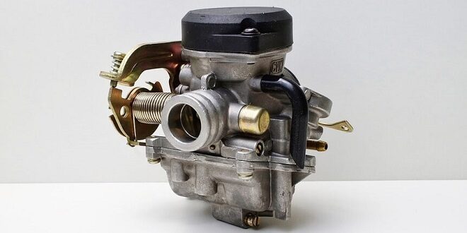
The modern-day carburetor is primarily comprised of a venturi tube, a tube that forms a throat to increase the velocity of the incoming air as it passes into the narrowest section and then decreases the velocity once the throat ends.
The venturi is mounted with a fuel capillary tube and throttle plate. It also employs a fuel reservoir, idle speed adjustment, idle valve, main metering needle valve, and choke.
Air enters the carburetor due to a pressure differential from a depression caused by the movement of the pistons in the cylinders. As the air travels through the venturi, it is accelerated and absorbs fuel droplets through Bernoulli’s principle.
Bernoulli’s principle states that as the air is accelerated through the venturi, there is a subsequent drop in pressure. The fuel which is at atmospheric pressure then is pushed through the capillary tube and forces droplets of fuel into the air stream. These fuel droplets then evaporate into the air stream producing an air and fuel mixture.
Last word
And if the engine reaches higher speeds, a higher pressure differential will increase the fuel mixture through the same principles, and conversely at slower speeds. A fuel reservoir is maintained through a float shut-off, which meters the entering fuel from the fuel line. The fuel line is fed from the gas tank through either an electric or mechanical fuel pump.